 |
Pen Plotter Project
|
|
Pen Plotter Project
|
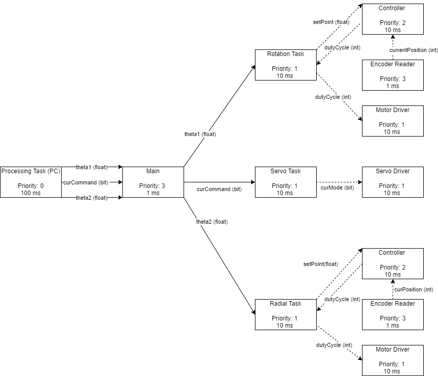
This section includes information regarding our pen plottor robot software design. Below in Figure 1 is a task diagram of all information that will be shared between tasks to accomplish our goal. To operate the robot, the user will run the main file and input an HPGL file that will be processed. The main file will then call the Processing Task which will place the current command (Pen Up or Pen Down) and the theta positions in revolutions that will be input to the radial, rotational, and servo tasks. The servo task will output a 0 or a 1 to the servoDriver based on whether the Pen needs to be UP (1) or DOWN (0). The radial and rotational tasks will output the setPoint in ticks to the controller task which calls the encoder task to calculate a duty cycle based on the proportional gain and encoder read values. This duty cycle is then input into the motor driver task to drive the motor.
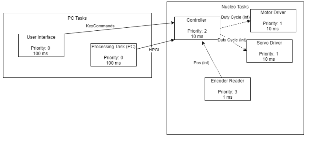
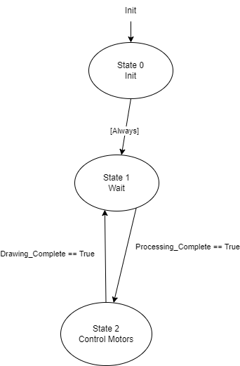
The previous Task Diagram could also be seen below in Figure 2. Some changes that we made are that we opted to have all the processing performed on the Nucleo, and we decided to have the User Interface built into the main file.
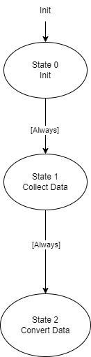
Once the user has input a drawing the processing task will convert the drawing to X and Y coordinates. From those X and Y coordinates, inverse kinematics will be used to translate X/Y to theta 1 and theta 2 motor positions in revolutions. This information is then added to two different queues and sent to either the Rotation or Radial tasks. A third queue called curCommand is also filled. This queue contains bits with the command Pen up (1) or Pen down (0). The curCommand queue is sent to the servo task
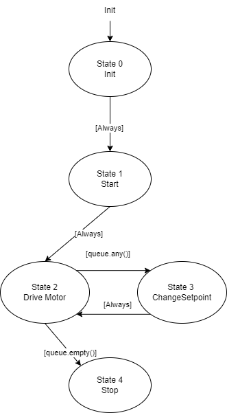
The rotation and radial tasks control the respective motor drivers, controllers, and encoders related to each motor. The rotation and radial task perform exactly the same so both will be described here. Once the theta 1 and theta 2 positions are in their respective queues, the desired setPoint in ticks is sent to the controller task. The controller task then calls the Encoder Reader to get the current position and returns a desired duty cycle to the rotation/radial task. This duty cycle is then inputted into the motor driver task.
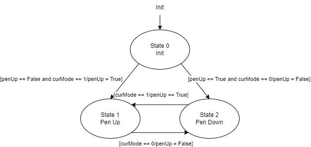
Servo task will initiate and alternate between two states: Pen Up or Pen Down depending on the desired command put in the curCommand queue. The desired mode is then sent to the servo driver.
Task controller will wait for a provided setPoint from the Rotation or Radial Tasks and use path data with a proportional gain input to send PWM signals to respective motors tasks.
Task motor driver will recieve PWM duty cycles from the rotation or radial tasks and apply the signal to instantiated motors.
Task servo driver will receive curMode commands from the servo task and apply the signal to the servo.
Task encoder will be the highest priority, constantly sending motor positions for radial and angular motors. Task controller will receive these values and interpret them to vary PWM for motors.